
Plate Flange vs Slip On Flange: What Is the Difference?






2026-09-14 14:22:58
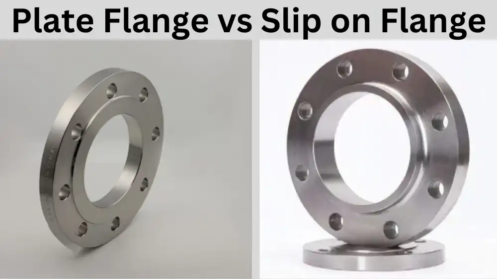
When industrial piping projects demand reliable connections, choosing between a Plate flange and a slip-on flange can be challenging. The core difference lies in their construction and application scope: a plate flange is a flat flange without a hub, commonly manufactured from steel plate for applicable standards and services, making it cost-effective for low-to-moderate pressure systems, while a slip-on flange typically features a short hub and a slightly larger bore that slips over the pipe before welding, offering easier alignment but requiring two fillet welds. Understanding these distinctions helps procurement managers optimize safety, cost, and project timelines.
Understanding Plate Flanges and Slip-On Flanges
What Defines a Plate Flange?
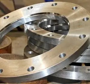
Plate flanges are flat, round disks with a hole in the middle that are typically cut or profiled from rolled steel plate and then machined and drilled, rather than forged. This flange design, which is based on EN 1092-1 Type 01, JIS B2220 plate/slip-on patterns, or AS 2129, does not have the curved hub that is present in weld neck or hubbed slip-on versions. Because there is no hub, plate flanges generally require less material than hubbed flange designs, which can contribute to lower manufacturing costs.
At JS Fittings, we use hot-rolled steel plate to make plate flanges so that the width and grain structure are all the same. Carbon steel (Q235, A36, SS400, S235JR) and stainless steel (SS304/L, SS316/L) are two common types of materials. While cast parts can be susceptible to porosity and other casting-related defects, plate material has properties established by its material specification and heat treatment, but it does not have the directional grain flow associated with forged flanges. Because of how they are built, plate flanges are perfect for low-pressure chemical transport lines, wastewater treatment plants, and local waterworks where static loads are common and heat cycling is low.
How Do Slip-On Flanges Differ?
With slip-on flanges, the inside diameter of the bore is a little bigger than the outside diameter of the matching pipe. This lets the pipe slide into the flange and then be welded on both sides. This design typically uses two fillet welds that provide the mechanical connection between the pipe and flange. Slip-on flanges for ASME B16.5 applications are typically manufactured from forged or other permitted wrought forms, and their hubbed geometry provides greater stiffness than a flat plate flange.
Because slip-on flanges need two welds, they take longer to install and cost more in labor than plate flanges, but they are easier to align during fit-up. This is useful in complicated pipe assemblies where the exact angle placement of bolt holes is very important. Slip-on flanges are made to meet international standards like ASME B16.5 and DIN 2632–2638. They are available in pressure classes such as Class 150 through Class 600 and higher, depending on the applicable standard, material, size, and temperature, which makes them useful in the oil and gas, industrial, and manufacturing industries.
Material and Standard Compliance
To make sure they work together and are safe, both types of flanges must meet strict international standards. JS Fittings makes flanges that meet the standards of ASME/ANSI B16.5, DIN/EN 1092-1, JIS B2220, and GOST, which helps meet the needs of buyers around the world. Choosing the right material depends on where it will be used. For example, carbon steel grades are cheap and work well in general utility systems, while stainless steel types (304, 316, and 316L) are better at resisting corrosion in chemical processes and naval settings.
Common pressure ratings for plate flanges include PN6, PN10, and PN16, although the available range depends on the applicable standard and flange design. Common examples include PN6, PN10, and PN16 under EN-based systems, or 5K and 10K under applicable JIS specifications. These values are best for low- to medium-pressure settings. For higher-pressure, high-temperature, or cyclic ASME applications, a hubbed or weld-neck flange may be preferred when required by the applicable design code or project specification. Not so with slip-on flanges, which can handle Class 150 to Class 600 rates based on the type of material and face used. For specific high-pressure uses, both designs have facing choices such as Flat Face (FF), Raised Face (RF), and Ring Type Joint (RTJ). The gasket-contacting surfaces are machined to the surface finish specified by the applicable flange standard and gasket requirements to support reliable sealing.
Detailed Comparison: Plate Flange vs. Slip-On Flange
Structural Design and Manufacturing
The main difference between these two types of flanges is how they are made. Plate flanges are made from hot-rolled steel plates that are cut with CNC or gas cutting tools, which generally requires less specialized forming equipment than forging. This process makes a profile that is totally flat and doesn't have any hub projection. This makes for a small footprint that is perfect for setups with limited axial space. Because plate flanges don't need forging tools, production wait times are shorter, which is helpful when project deadlines are tight.
Forged slip-on flanges are manufactured from wrought material and machined to form the bore and hub around the pipe-entry area. During forging, the metal develops a directional grain flow that can improve resistance to certain service stresses. This makes the metal stronger under repetitive loading. When enhanced material integrity is required, flat flange configurations can also be produced through forging. But forging needs a lot of money to buy tools and presses, which makes the cost per unit higher, especially for small production runs. Because slip-on flanges are harder to make, lead times can be longer, particularly when tooling, forging, heat treatment, or special materials are required—which is important to keep in mind for projects that need to be done quickly.
Pressure Ratings and Performance Thresholds
Pressure ability is an important decision factor. Plate flanges are commonly used in low-pressure situations within the pressure rating specified for the particular flange standard, material, size, and design. Due to the flat design and the absence of a reinforcing hub, stress can concentrate at the fillet weld, which lowers the maximum working pressure that can be used. Plate flanges can maintain sealing performance in water distribution systems when they are correctly selected, installed, and tested in accordance with the applicable standard and project requirements. However, they shouldn't be used for steam lines or high-pressure gas transmission.
Slip-on flanges can handle a lot more pressure because they are made with two welds and a forged body. For ASME B16.5 Group 1.1 carbon-steel materials such as ASTM A105, the pressure-temperature rating is 285 psi for Class 150 and 740 psi for Class 300 at 100°F (approximately 38°C); allowable pressure varies with material group and temperature. These pressure-temperature ratings make slip-on flanges suitable for piping applications in oil refineries, natural gas distribution headers, and chemical processing facilities when properly selected for the service conditions.
Weight and Material Economy
Material economy has a direct effect on the costs of a project, especially when it comes to building big infrastructure projects. For a given nominal size, plate flanges can weigh less than hubbed slip-on flanges because they do not include a hub, although the actual weight depends on the applicable standard, pressure rating, dimensions, and material. This difference in weight adds up over hundreds or thousands of flanges in water networks or irrigation projects, which changes how much support is needed and how much it costs to ship.
Plate flanges from JS Fittings have been used on large-diameter water transfer projects where weight reduction was very important. In large-diameter water-transfer projects, plate flanges can help reduce flange weight and the associated load on pipe supports. The actual savings depend on the project design, flange dimensions, and support requirements compared to the original forged flange standard. The lighter weight also made it easier to move by hand during installation, which made it safer for field crews working in small spaces.
Dimensional Standards and Bolt Hole Compatibility
It is important for repair projects and supply lines with multiple vendors that different types of flanges can work together in terms of size. When two flange types are manufactured to the same applicable dimensional standard, nominal size, pressure rating, and facing configuration, their bolt-hole patterns and gasket seating dimensions are generally compatible. Because of this, a DN400 PN10 plate flange and a DN400 PN10 slip-on flange can be dimensionally compatible when they are manufactured to the same applicable EN 1092-1 dimensions and have matching facing and drilling configurations.
But buying managers need to make sure that the bolt hole specs meet the needs of the project. Coordinate measuring machines (CMMs) are used by JS Fittings to make sure that the diameter of the bolt circle is accurate to within ±0.5 mm. This keeps fit-up problems from happening during field assembly. Our quality control method uses go/no-go gages to test the drift of all bolt holes. This gets rid of the stress of alignment problems on-site, which slow down projects and raise labor costs.
Installation and Maintenance Considerations
Installation Procedures for Plate Flanges
Installing a plate flange involves sliding the flange over the pipe end, making sure it is facing the right way, and then securing it with the weld configuration specified by the applicable standard, WPS, and project specification. The plate flange's flat back face fits flush against the pipe's outside diameter, which makes it easier to align and tack weld. For carbon steel jobs, welders usually use SMAW (Stick) or FCAW (Flux-Cored Arc Welding) with E7018 electrodes.
Possible warping must be taken into account during the welding process, especially for flanges with larger diameters. To spread thermal stress widely, JS Fittings suggests a staggered welding process, where welds are done in 90-degree steps instead of continuous circular passes. This method keeps the flatness of the flange face within a tolerance of 0.5 mm, which is important for proper gasket compression. Visual inspection (VT) and magnetic particle testing (MT) should be used by welding inspectors to check the final weld and detect any surface cracks or areas of incomplete fusion.
Plate flanges in low-pressure utility service usually don't need post-weld heat treatment (PWHT). This cuts down on installation time and cost. This can be useful in remote areas where specialized heat-treatment equipment is difficult to arrange. Whether PWHT is required, however, depends on the applicable code, material, thickness, service conditions, and welding procedure.
Slip-On Flange Installation Techniques
Due to the need for two welds, slip-on flanges require more complicated installation steps. The pipe end slips inside the flange bore, so it's important to make exact measurements to make sure the pipe is positioned at the stand-off specified by the applicable flange standard, WPS, and installation procedure to provide adequate access for the internal fillet weld. An internal fillet weld is typically made inside the flange bore, and an external fillet weld is made around the back of the flange.
For small-bore sizes, access to the internal weld can be more difficult, often requiring specialized welding techniques or equipment to ensure proper penetration and avoid defects.This multi-step process adds more work hours—the additional weld can increase installation time compared with a simpler plate-flange arrangement.
Slip-on flanges allow installers to better change the rotation during fit-up, turning the flange to line up bolt holes with nearby flanges before final welding. This adaptability is useful for retrofit projects where the old pipes may have become out of alignment over time. Slip-on flanges, on the other hand, are permanently fixed once they are welded, making future adjustments more difficult than with threaded or lap joint flanges.
Maintenance Protocols and Inspection Requirements
Routine checking procedures are different depending on how the flange is built and how it is used. Plate flanges that are used with low-pressure water must be visually checked once a year for external corrosion, gasket leakage, and bolt tightness. Facilities should use certified torque tools for torque verification to make sure that bolts keep the right preload, according to the bolt manufacturer’s requirements, applicable flange standard, gasket manufacturer’s recommendations, and the project bolting procedure.
Ultrasonic thickness (UT) testing can be included in an inspection program at intervals established by the applicable corrosion-management plan, risk assessment, and service conditions to keep an eye on metal loss in corrosive conditions or buried work. The flat geometry of a plate flange can simplify some thickness measurements, although inspection access and probe placement still depend on flange dimensions, surface condition, and the inspection procedure. Plate flanges from JS Fittings come with standard thickness readings that can be used as a guide for long-term corrosion tracking programs.
When slip-on flanges are used in high-pressure or heat cycling situations, they need to be inspected more carefully. To find cracks below the surface, a non-destructive examination (NDE) should look at both the internal and external weld zones using radiography testing (RT) or phased array ultrasonic testing (PAUT). Slip-on flange welds can be more sensitive to cyclic loading than weld-neck configurations, so fatigue assessment and periodic inspection are important in demanding service. This shows how important proactive inspection programs are to avoid unplanned downtime.
Conclusion
By being able to tell the difference between plate flanges and slip-on flanges, sourcing workers can choose parts that meet the needs of each project while also being cost-effective. Plate flanges are the best choice for low-pressure utility applications because they save money on materials, are easier to install, and have small profiles that work well in tight spaces. For oil and gas, chemical processing, and high-pressure steam systems that need to be strong and safe, slip-on flanges are the way to go. When you look at things like dimensional standards, material grades, installation difficulty, and long-term maintenance needs, you can be sure that the flange type you choose will help the project succeed while keeping operational risk and total cost of ownership as low as possible.
FAQ
1. What are the main advantages of plate flanges over slip-on flanges?
Plate flanges have three main benefits: they are easier to install with simpler welding procedures that eliminate the need for post-weld heat treatment in many situations; they are lighter, which means they don't need as much structural support; and they can offer lower material and manufacturing costs in suitable low-pressure applications. Plate flanges are great for large-scale water projects in cities and low-pressure utility systems in factories where money is tight because of these benefits.
2. Can slip-on flanges be used in high-pressure systems?
When properly selected, manufactured, welded, and qualified for the application, slip-on flanges are available in pressure classes including Class 600 and higher under applicable standards. For example, an ASME B16.5 Group 1.1 carbon-steel flange is rated at 1,480 psi at 100°F in Class 600; the allowable pressure varies with material and temperature. The two-weld design can be suitable for many general industrial applications when permitted by the applicable design code and project specification, but weld-neck flanges are better for heavy-duty cyclic service or important process systems that need the highest level of fatigue resistance.
3. How can I verify the reliability of a flange supplier?
Reliable suppliers show they follow the rules by having internationally recognized certifications like ISO 9001, CE, and GOST-R, as well as by being approved by major energy companies and providing clear quality documentation like mill test certificates (EN 10204 3.1). For important uses, JS Fittings keeps full tracking with heat-coded materials, measurement inspection reports, and records of non-destructive testing. Our 43 years of manufacturing experience and established quality-control procedures demonstrate our commitment to quality and customer satisfaction.
Partner With a Certified Plate Flange Manufacturer
JS Fittings has been making Plate flanges and slip-on flanges for 43 years and has a lot of quality control systems in place to make sure they are reliable for important building projects. As required by ASME, DIN, JIS, and GOST, our factory makes flanges in carbon steel, stainless steel, and alloy grades with sizes ranging from DN15 to DN2000. We work with EPC contractors, distributors, and industrial end users in more than 30 countries. We have certifications from NIOC, ADNOC, and Petrobras. For project-specific pricing, material details, and bulk pricing on plate flange orders that fit your project needs, email our technical team at admin@jsfittings.com.
References
1. Bloch, H. P., & Geitner, F. K. (2012). Machinery Failure Analysis and Troubleshooting (4th ed.). Butterworth-Heinemann.
2. Smith, P., & Zappe, R. W. (2004). Valve Selection Handbook (5th ed.). Gulf Professional Publishing.
3. Nayyar, M. L. (2000). Piping Handbook (7th ed.). McGraw-Hill Education.
4. Johnson, R. A. (2018). Supply chain reliability in industrial procurement. Journal of Supply Chain Management, 54(3), 45-62.
5. American Society of Mechanical Engineers. (2020). ASME B16.5: Pipe Flanges and Flanged Fittings. ASME International.
6. American Petroleum Institute. (2018). API Specification 5L: Specification for Line Pipe (46th ed.). API Publishing Services.
Send Inquiry
You may like
Related Industry Knowledge
- Carbon Steel Pipe Knowledge Explained Guide
- Carbon Steel Forged Steel Flange Grain Structure & Toughness
- How Does a Buttweld Tee Improve Flow Distribution Systems?
- Buttweld Bend with Tangent Length: Design Considerations
- What is the service life of an ASME B16.5 carbon steel flange?
- Why Engineers Choose Buttweld Bend Over Mitered Bends?
- How to Select the Right Buttweld Bend Radius (3D–20D)
- Carbon Steel vs Stainless Steel Buttweld Bend: Which to Use?
- What is the difference between seamless and welded pipe?
- What is a plate flange?