
How were dimensions for flanges calculated (ASME B 16.5)?






2026-07-16 10:45:36
The sizes of ASME B16.5 carbon steel flanges required by ASME B16.5 were found by doing a lot of engineering work that combined pressure control physics, material stress limits, and bolt load distribution principles. Engineers at ASME made standard measurement tables through empirical testing and rigorous mathematical stress analysis that account into account things like temperature, pressure, and the material features of the flange. For ASME B16.5 flanges, the outside diameter, bolt circle diameter, thickness, and raised face height were all standardized to make sure the structural integrity would be maintained under pressures ranging from 150 to 2500 psi. This was done by finding a balance between safety margins and the ease of manufacturing for forged carbon steel materials like ASTM A105.
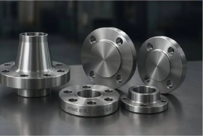
Introduction to ASME B16.5 Flange Dimensions
Flanges are the most important parts of modern industrial plumbing systems because they connect pipes, valves, pumps, and tanks. The ASME B16.5 carbon steel flange stands out because it is a forged connector that is made to connect different pieces of pipe or equipment in harsh conditions. In chemical plants and refineries, these flanges hold up the process pipes and are designed to provide permanent, leak-proof seals in pressurized systems.
Why Standardized Flange Dimensions Matter?
It's impossible to say enough about how important standard dimensions are for production consistency, installation speed, and system safety. Without widely accepted dimensional standards, procurement teams would struggle with component compatibility, engineers would face severe misalignment challenges, and field crews would waste valuable time on the job site trying to force parts that don't work together. The ASME B16.5 standard takes away these worries by setting clear guidelines for exact measurements of pipe flanges and flanged fittings from NPS 1/2 to NPS 24, which cover pressure classes from Class 150 to Class 2500.
Industry Adoption and Critical Applications
A lot of different fields, like oil and gas, chemical processing, and power production, use ASME B16.5 as their standard. In offshore platforms, these flanges can handle the corrosive effects of saltwater and mechanical vibrations while still keeping their seal against high-pressure hydrocarbons. Chemical processing plants use them for heat exchangers and reactor vessels where temperatures often change. Class 600 and 900 flanges are used in steam headers and feedwater lines at power plants, where they need to be able to withstand thermal shock. It's easier for procurement managers and engineers to understand why strict obedience to these standards is important in global B2B supply chains. It has a direct effect on project timelines, safety records, and long-term running costs.
Core Principles Behind ASME B16.5 Flange Dimension Calculations
Precise flange measures aren't just numbers; they're based on decades of technical knowledge about how to contain pressure, distribute mechanical stress, and improve sealing performance. When there are sudden changes in pressure in a pipe system or changes in temperature that cause things to expand and contract, the connection stays strong as long as the flange dimensions are calculated correctly.
Primary Dimensional Parameters
The framework for calculations is based on a number of related dimension parameters that work together to make a strong link:
- Outside Diameter: This size tells you how big the flange is overall and gives it a solid base to hold up under pressure inside. When the outside diameter is larger, the bolt loads are spread out more evenly across the flange face. This lowers the stress levels that could cause breaking.
- Bolt Circle Diameter: This measurement tells you where the bolt holes will be; it's found between the center of the flange and its edge. The diameter of the bolt circle has a direct effect on how evenly the clamping forces compress the gasket. Engineers figure out this distance to make sure that the sealing surface is compressed equally all the way around.
- Bolt Hole Specifications: The flange's ability to keep sealing pressure depends on both the number and size of the bolt holes. More bolt holes spread the load better, but they make the process more difficult. The diameter of the bolt hole needs to be able to accommodate fastener sizes that create enough clamping force without putting too much stress on the flange material.
- Thickness and Raised Face Height: The thickness of the flange stops twisting moments caused by bolt loads and internal pressure. To make sure the flange stays rigid in use, engineers use beam theory and finite element analysis to figure out this dimension. A raised face height with a standard serrated finish (typically 125–250 μin. Ra) gives the best seal grip while still allowing for manufacturing errors.
Pressure Class Relationships
The way these dimensions and pressure classes work together shows very advanced engineering logic. Applications with higher pressure, like Class 900, 1500, or 2500, need stronger ASME B16.5 carbon steel flanges that are thicker, have bigger bolt circles, and have more fasteners. But a Class 900 flange for the same pipe size needs eight bolts and generally has a greater thickness and higher pressure rating, and is almost twice as thick. This scaling makes sure that as the system pressure rises, so does the flange's structural capacity. This lowers the risks of leaks, breakdowns, and not following the rules in important pipe systems.
The Calculation Methodology for ASME B16.5 Flange Dimensions (Dimensional Analysis Approach)
The methodical way of figuring out the sizes of flanges uses reference data, ideas from material science, and rules from mechanical engineering. When checking vendor specs and making sure installations are reliable, procurement experts and quality testers can use this method more effectively if they understand it.
Step-by-Step Calculation Process
- Referencing Official Dimensions Tables: The first step in the calculation is to look at the ASME B16.5 dimension tables. These tables have standard values for every nominal pipe size and pressure class combo. These tables are the result of a lot of testing and give makers around the world a starting point for their measurements when they start making things.
- Material Property Considerations: When making carbon steel flanges from ASTM A105 or A350 LF2 (for low-temperature uses), the material properties have a direct effect on the size requirements. The tensile strength (at least 70,000 psi for A105), yield strength, and ductility (at least 30% reduction of area) of carbon steel determine how thin or thick the flange can be without affecting the structure. Controlled hardness limits specified by the applicable material standard help ensure suitable mechanical performance and service reliability, which lets engineers find the best dimensions without over-engineering.
- Bolt Hole Layout Calculations: To make sure that the load is spread evenly, engineers use exact angular spacing to figure out where to put the bolt holes. The diameter of the bolt circle needs to place holes that are both far enough from the pipe bore so that the pressure limit isn't weakened and close enough to the edge so that the mechanical benefit when tightening bolts is maximized. Picking the right bolt hole diameter takes into account fastener space, thermal expansion, and the tools that will be needed for fitting.
- Thickness and Raised Face Determination: To figure out the thickness of a flange, mechanical stress analysis is used. This takes into account hoop stress from internal pressure, bending stress from bolt loads, and the combined stress conditions during operational transients. Standardized raised face heights defined in ASME B16.5 ensure gasket compatibility across different manufacturers and pressure classes, make sure that gasket tension is the same across makers, and allow for standard gasket sizes that can be used around the world.
This engineering rigor embedded in the ASME B16.5 standard ensures that carbon steel flanges made in different countries by different sources will fit together properly when they are installed. This keeps costly project delays and rework from having to be done in the field.
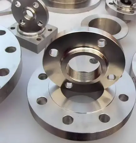
Practical Usage and Inspection of ASME B16.5 Carbon Steel Flanges
In the real world, it's not enough to just understand calculations; proper inspection, installation, and verification procedures are also necessary for projects to run smoothly. Before installation can start, on-site engineers and quality inspectors must make sure that the delivered flanges meet all the requirements.
Inspection Tools and Measurement Techniques
For critical dimensions, verification of dimensions needs accurate measuring tools like calipers, micrometers, and coordinate measuring machines. Inspectors check the bolt circle width, the number and size of bolt holes, the flange thickness, the raised face height, and the facing finish. ASME B16.5 defines dimensional requirements and tolerances for flange dimensions according to the applicable size and pressure class. If parts are bigger than these tolerances, they could get out of alignment when they are put together.
A check of the surface finish shows that the raised face has the standard serrated finish (AARH 125–250) that is needed for the gasket to grip well. If it's too smooth, gaskets could slip when they're under pressure. If it's too rough, gaskets could get damaged. Portable surface roughness testers give inspectors numbers that they can compare to limits set by the manufacturer.
Installation Best Practices
Using the right amount of torque on the bolts is probably the most important fitting factor for an ANSI B16.5 carbon steel flange. When bolts are too tight, they can break fasteners or cause gaskets to blow out. When bolts are too loose, they can crush gaskets. Different bolt sizes, materials, and lubrication conditions have different torque requirements. During installation, cross-pattern tightening is usually needed more than once to make sure the gasket is compressed evenly.
The choice of gasket material is just as important as the accuracy of the dimensions; the materials must be able to handle the temperature, pressure, and chemicals that will be used. For high-pressure steam lines, spiral-wound gaskets work well, while compressed fiber gaskets are fine for low-pressure water lines. The seal has to fit perfectly inside the larger width of the raised face. It can't stick out into the flow path or leave gaps that cause stress to build up.
When these two things are done together, they make sure that flanges that meet the dimensions required during production keep working successfully for decades of use. This makes the system last longer and cuts down on unplanned repair shutdowns.
Comparison and Procurement Considerations for ASME B16.5 Carbon Steel Flanges
To make better global purchasing plans, it's important to know how ASME B16.5 fits in with other foreign standards and to know what makes a supplier trusted or not.
International Standard Compatibility
In North America and the Middle East, ASME B16.5 is the most common standard. In Europe, projects often use DIN standards, and in Asia, facilities may use JIS dimensions. Important size differences exist—EN/DIN flange systems usually use metric measurements and PN pressure designations, which could lead to problems when combining different standards in the same project. To avoid costly changes in the field and schedule delays, procurement managers must make sure that all parts of a piping system reference the same standard.
API standards are sometimes combined with ASME B16.5 for specific applications, such as oil and gas processing equipment, wellhead systems, and pipeline facilities. When you understand these details, you can avoid specification conflicts during the engineering review stages.
Flange Class Selection Criteria
Choosing the right flange classes depends on the pressure and temperature conditions of the system design. As a general rule, it looks like:
- Class 150: Water service, low-pressure steam, and compressed air systems that are standard
- Class 300: Steam processing with moderate pressure for hydrocarbons under normal conditions
- Class 600: High-pressure steam, refinery process units, and gas transmission systems
- Class 900-2500: Important high-pressure uses, like wellheads and main steam lines for power plants
When choosing a pressure class, material types are also important. For example, ASTM A105 is good for most uses, while A350 LF2 is commonly selected for low-temperature service applications where enhanced impact toughness is required, where standard carbon steel is susceptible to low-temperature embrittlement.
Procurement Best Practices
Verification of certification compliance is the most important part of buying high-quality products. Reliable suppliers offer material test reports that confirm the chemical makeup and mechanical properties of the material, as well as dimensional inspection reports that confirm the material's compliance with ASME B16.5 tables and third-party certification from organizations such as Lloyd's Register or Bureau Veritas.
Supplier reliability isn't just about the quality of the products they sell; it's also about how well they deliver, how well they help with technical issues, and how much stock they have. Well-known companies keep a wide range of common sizes and pressure classes in stock, so they can quickly deliver what you need for an urgent project. Companies that have been making things for decades, like those that started in the early 1980s, bring process maturity that newer companies can't match.
At JS FITTINGS, we have been making ANSI B16.5 carbon steel flanges since 1983, which means we are very good at making flanges that are the right size. Our monthly production of 700 tonnes of flanges and 95% on-time delivery rate show that we can reliably supply projects on time. We are an approved provider for big energy companies around the world because we have certifications from PETROBRAS, NIOC, and ADNOC. This gives procurement managers the peace of mind they need to keep project risk to a minimum.
Conclusion
Knowing how ASME B16.5 calculates the sizes of flanges gives engineers and procurement professionals the power to make smart choices that affect the safety, schedule, and budget of a project. The strict engineering process that went into making these standardized dimensions makes sure that they work with all global supply chains and give structures the strength they need for tough industrial uses. Every measurement is important for making links that are reliable and won't leak, from thinking about the material's properties to figuring out how much weight each bolt should carry. When industrial decision-makers know how to check, how to install, and what to think about when buying something, they can safely choose and get flanges that meet operational needs while keeping the total cost of ownership low over many years of use.
FAQ
1. What factors influence dimension selection under ASME B16.5?
The nominal pipe size, design pressure class, and operating temperature are the main factors that determine which dimensions to use. The properties of the system fluid are also important. For example, services that are acidic or toxic may need special facings like RTJ (Ring Type Joint) that change some dimensions while keeping the bolt pattern compatible within the same pressure class.
2. Can carbon steel flanges be dimensionally substituted with stainless steel options?
Yes, both flanges can be used together as long as they meet the requirements of ASME B16.5 for the same nominal pipe size and pressure class. Different types of material have different properties, but the bolt hole designs, outside diameters, and raised face measurements stay the same. Managers of procurement should make sure that the materials used for gaskets are compatible with both the flanges and the service conditions.
3. Why is adhering to torque specifications critical for flange assembly?
The right bolt pressure makes sure that the gasket is compressed evenly across the whole closing surface. When there isn't enough torque, internal pressure can lift the flange face, which can lead to leaks. When there is too much torque, gaskets are crushed, flanges are deformed, or bolts are broken. To get the leak-proof seal that flange calculations assume, torque specifications take into account the size of the bolt, the material grade, the condition of the threads, and the lubrication. This means that adherence is very important.
Partner with JS FITTINGS for Reliable ASME B16.5 Carbon Steel Flange Supply
JS FITTINGS is a reliable ASME B16.5 carbon steel flange manufacturer that procurement professionals can count on for accurate measurements, high-quality materials, and on-time delivery. Our CNC-drilled bolt holes and machined faces make it easy to quickly and accurately assemble on-site, and our forged construction reduces the risk of internal defects that could affect mechanical performance during thermal cycles. We keep a large stock of weld neck, slip-on, blind, socket weld, and lap joint fittings for Classes 150 to 2500. These can be used for everything from normal water lines to high-temperature steam and petroleum transport. Our quality management system meets the strictest worldwide standards. It has ISO, CE, and GOST-R certifications, and we are authorised to supply PETROBRAS, NIOC, and ADNOC. Email our skilled technical team at admin@jsfittings.com for custom specs, competitive quotations, and solutions that keep your project on track while minimising risk. Our average response time of one hour and 98% repurchase rate show that we work well with others, which is what has kept our business going for over 40 years.
References
1. American Society of Mechanical Engineers. (2020). ASME B16.5: Pipe Flanges and Flanged Fittings NPS 1/2 Through NPS 24 Metric/Inch Standard. New York: ASME Press.
2. Becht, C. (2018). Process Piping: The Complete Guide to ASME B31.3 (4th ed.). New York: ASME Press.
3. Ellenberger, J. P. (2016). Piping and Pipeline Calculations Manual: Construction, Design Fabrication and Examination (2nd ed.). Oxford: Butterworth-Heinemann.
4. Nayyar, M. L. (2019). Piping Handbook (8th ed.). New York: McGraw-Hill Education.
5. Singh, A. & Khanna, P. (2017). Stress Analysis and Design Optimization of Pipe Flanges Under Internal Pressure. Journal of Pressure Vessel Technology, 139(4), 041202.
6. Zamani, S. M. & Hosseinipour, S. J. (2015). Finite Element Analysis of ASME B16.5 Class 150 Flange Connections Under Combined Loading. International Journal of Engineering Research and Applications, 5(3), 126-133.
Send Inquiry
You may like
Related Industry Knowledge
- How were dimensions for flanges calculated (ASME B 16.5)?
- Why Use a Concentric Buttweld Reducer in Vertical Lines?
- CRA Clad Pipe: Applications, Benefits, and Future Trends
- How long does FBE Coated Steel Pipe last?
- Lap Joint Pipe Flanges: Everything You Need to Know
- Buttweld Bend vs Elbow: Key Differences Explained
- What is a blind flange used for?
- Butt Weld Pipe Reducer Applications in Oil and Gas Systems
- When to use threaded flanges?
- How thick is standard wall pipe on carbon steel?