
Why Use a Concentric Buttweld Reducer in Vertical Lines?






2026-07-16 10:45:32
Choosing the right fitting is very important when changing pipe diameters in vertical installations. If you don't, your system might not work reliably, and you'll have to pay a lot for downtime. A buttweld reducer designed for vertical use needs to keep the centerline straight, stop turbulence, and get rid of any flow interruptions that could make things less safe and less efficient. Concentric reducers are commonly used in vertical lines because their symmetrical shape helps maintain a centered flow path. This stops air from getting trapped and evens out the pressure, which can happen at badly designed transitions. This guide walks engineering and procurement professionals through the technical benefits, selection criteria, and actual installation issues for vertical piping systems.
Understanding Concentric Buttweld Reducers in Vertical Lines
Fundamental Design Characteristics
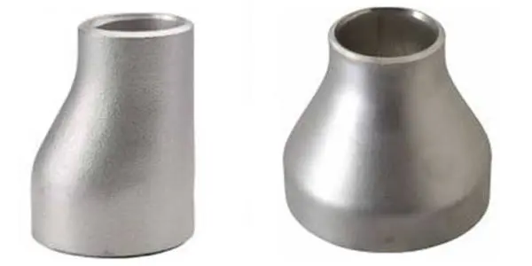
The body of a concentric reducer is made like a cone, and the inlet and outlet share the same centerline. This perfect taper makes the pipe width smaller over time while keeping the fluid in the middle of the pipeline. The shape makes a smooth flow path that reduces turbulence and stops pressure spikes in certain areas. Engineers choose concentric designs for vertical lines so that gravity-driven flow has a uniform cross-sectional reduction without any offset angles that could stop fluid movement going up or down.
How does a concentric configuration differ from an eccentric one?
Some horizontal problems can be solved by eccentric reducers, which have flat sides that keep air from building up in pump suction lines. When gravity needs to separate gas from liquid, the off-center axis keeps the top or bottom of the pipe remaining level. These problems are generally less common in some vertical setups because buoyancy effects can help separate gas and liquid phases along the pipe path. Whether your pipeline runs horizontally or vertically will determine which type to use (concentric or eccentric). This choice will have an impact on the long-term stability of your operations.
Integration into Vertical Pipeline Systems
Putting in a concentric buttweld reducer in a vertical process column or transfer line makes sure that changes in fluid speed happen slowly. It stops rapid expansion or contraction that could cause cavitation zones or erosion damage by having a tapered shift. Vertical columns are often used to connect equipment operating at different flow rates in chemical processing plants, factories, and power plants. A reducer of the right size can handle these changes while still keeping the structure strong for high-pressure steam, corrosive chemicals, or rough slurries.
Key Benefits of Using Concentric Buttweld Reducers in Vertical Lines
Balanced Flow and Pressure Stability
For process control, vertical piping systems need consistent pressure conditions. Concentric reducers spread changes in velocity evenly across the cross-section of the pipe. This stops the swirling eddies that cause changes in pressure. This steadiness is important for controlling gravity-fed discharge rates or pumping fluids up tall buildings. This predictable hydraulic behavior is useful for engineers because it makes system modeling easier and lowers the chance of sudden pressure surges that could damage equipment further downstream or cause safety shutdowns.
Simplified Installation and Maintenance
When working vertically with a buttweld reducer, the symmetrical shape makes welding easier. It's easier for pipe fitters to get both ends lined up straight when they share a centerline. This means they don't have to do as much complicated jigging or repositioning. This makes it easier to install and faster, which saves time and money on labor, especially in small spaces where getting to things is already hard. Simple geometry is also helpful for maintenance inspections because inspectors can check the quality of the weld and the thickness of the wall without having to worry about offset angles that make ultrasonic testing more difficult.
Material Durability for Harsh Environments
Concentric buttweld reducers made of high-quality materials can handle the tough situations in industry vertical lines. Types of carbon steel, like ASTM A234 WPB, are widely used for pressure piping applications when properly selected according to design conditions, and types of stainless steel, like ASTM A403 WP316L, don't rust in places where chemicals are processed. Power plant steam lines often use alloy steel fittings such as A234 WP11 and WP22 for elevated-temperature pressure applications. Each choice of material takes into account different types of practical pressures, such as mechanical, thermal, or chemical ones. This makes sure that the product lasts a long time without breaking down early.
Engineers can match pressure ratings to system needs because wall thickness can be selected according to the connected pipe schedule requirements, ranging from light-wall to heavy-wall configurations. When the total pipe mass is limited by structural support, thinner schedules are used to save weight. Thicker walls can handle higher internal pressures and external loads. This gives designers the freedom to make the most of both project budgets and safety margins.
Standards Compliance and Quality Assurance
Manufacturing components in accordance with ASME B16.9, EN 10253, DIN 2616, and MSS-SP-75 ensures precise dimensional uniformity and reliable material properties.Tolerances are set by these guidelines for length from end to end, outside diameter, difference in wall thickness, and bevel angles. Compliance makes sure that reducers from certified sources work well with other code-compliant parts, so there are no problems with fit-up during building. Documentation of quality, such as Mill Test Certificates per EN 10204 3.1, makes it possible to track heat numbers, chemical composition, and mechanical properties. This is important for regulatory checks and warranty claims.
Comparison: Concentric vs. Eccentric Buttweld Reducers for Vertical Lines
Structural and Functional Geometry Differences
An eccentric reducer's off-centerline makes an asymmetric flow path that works well for horizontal installations, where keeping one side flat keeps air from building up. This feature isn't very useful for vertical lines because buoyancy forces already separate phases along the pipe axis. Concentric shapes help maintain a balanced flow path, which can reduce localized turbulence and erosion risks in abrasive service. Which design to use depends on the pipe direction and the properties of the fluid. For example, vertical columns that handle single-phase gases or liquids almost always work better with concentric transitions.
Application Suitability for Vertical Installations
Most of the time, concentric buttweld reducers are used vertically in process towers, distillation columns, and chemical reactors. When joining column parts or moving from one processing stage to the next, their aligned shape helps keep the flow even. Eccentric variants may show up in vertical pump discharge lines where the orientation changes from vertical to horizontal, needing the flat-side orientation to keep air from sticking to the pipe. Knowing when each type applies keeps you from having to make expensive changes to the field and makes sure that the system works reliably from the start.
Pressure Rating Considerations
When made to the same schedule and grade of material, both configurations have the same pressure ratings. The pressure capacity is based on the wall thickness, not the centerline arrangement. The internal pressure that a Schedule 80 concentric reducer in A234 WPB handles is the same as that of its eccentric cousin. To choose the right schedule, you have to figure out the design pressure, how temperature affects the strength of the material, and any safety factors that apply from the code. Higher static head pressures are common at lower elevations in vertical installations. This means that the bottom parts of tall columns need to have thicker walls. Reliable manufacturers provide reducers produced precisely to these requirements.
Material Selection for Specific Industrial Needs
Carbon steel is good for general industrial use where resistance to corrosion isn't important, and temperatures stay moderate. When working with corrosive fluids like acids, caustics, or chlorinated compounds, you need to use stainless steel. When the temperature goes above 650°F, carbon steel starts to lose its strength, and creep resistance becomes an important design factor. For low-temperature services, ASTM A420 WPL6 material with suitable impact toughness may be selected according to the design temperature requirements to prevent brittle fracture. Matching the properties of the material to the real working conditions stops failures before they happen and increases the time between repair visits.
When used in vital high-pressure service, seamless construction is stronger and removes the chance of weld seam failure. Welded reducers are cheaper and can fit larger widths than seamless ones can. Sizes larger than 24 inches are often produced using plate-formed welded construction, depending on design requirements. Whether you choose seamless or welded depends on the diameter you need, the pressure rating, and your budget.
How to Select and Install a Concentric Buttweld Reducer in Vertical Pipelines?
Selection Criteria Based on Application Requirements
Engineers begin by figuring out the nominal pipe sizes at the inlet and outlet. Then, they use operating conditions to figure out the required pressure rating. Schedules for wall thickness must meet or go beyond the design pressure estimates, with enough room for error. The choice of material is based on how well it works with the fluid, the temperature range, and natural factors such as physical effects or corrosion from the outside. Standard size ranges commonly include smaller seamless sizes, while larger diameters are often produced using welded construction, depending on requirements, and larger diameters up to 80" x 72" can be made with welding.
Standard Dimensional Ranges and Custom Options
Standard buttweld reducer sizes are set by ASME B16.9 based on pipe schedules. This makes sure that products from different manufacturers can work together. The standard includes lengths from end to end that are figured out by diameter ratios, outside diameters that match pipe schedules, and bevel angles that are prepared according to ASME B16.25 welding end requirements. These standard sizes make it easier for distributors and contractors to keep track of their stock for multiple projects and allow for interchangeable sourcing.
For non-standard uses, longer body lengths may be needed to get softer taper angles in high-speed services, or special bevels may be needed to fit walls of different thicknesses. For mounting sensors or installing sample ports, some setups need reducers with straight tangents that are longer on one end. Clear communication of these needs during procurement avoids costly changes in the field and project delays.
Installation Best Practices for Vertical Welding
Before installing something correctly, the pipe ends and reducer bevels need to be cleaned well to get rid of mill scale, rust, and other contaminants that could affect the quality of the weld. To get accurate alignment in a vertical position, you need temporary supports or positioning that keeps the axis straight during the welding process. Gravity pulls molten metal for welding downhill, so welders have to adjust their welding technique and travel speed to keep the metal from sagging or incomplete fusion. Using qualified welding techniques that are designed for vertical positions ensures that the mechanical properties and penetration are always the same.
Avoiding Common Installation Pitfalls
Misalignment during fit-up creates stress concentrations that can initiate fatigue cracks during cyclic operation. Using proper alignment tools and checking concentricity before tack welding prevents this issue. If you don't preheat thick-wall carbon steel properly, hydrogen cracking will happen in the heat-affected zone. This risk is eliminated by following the preheat tables during welding procedures. When you rush through the welding process without controlling the temperature between passes properly, you end up with hard spots that aren't as tough. Taking the time to follow approved methods may slow down progress at first, but it prevents costly field repairs and potential safety hazards.
Conclusion
When you choose concentric buttweld reducers for vertical piping systems, you get operational benefits like centered flow paths, easier installation, and proven dependability in harsh industrial settings. Their symmetrical shape keeps the pressure stable and reduces turbulence, and they are safe and high-quality because they meet international standards. Knowing the technical differences between concentric and eccentric setups, along with the right way to choose materials and install them, helps engineers and procurement professionals choose parts that improve system performance and keep project costs low. Working with certified manufacturers who offer full documentation and engineering support makes project results even better and increases the long-term dependability of assets.
FAQ
1. What distinguishes concentric from eccentric buttweld reducers?
Concentric reducers keep the centerline of the inlet and exit the same. This makes symmetrical flow lines that are perfect for setups that go up and down. Offsetting centerlines on eccentric reducers keeps one side flat, which keeps horizontal pump pressure lines from getting air pockets. The choice of geometry depends on the orientation of the pipe and the properties of the fluid. For example, vertical lines work best with concentric alignment, while horizontal configurations usually need eccentric designs.
2. Can concentric reducers work effectively in horizontal piping systems?
Concentric reducers work well in horizontal lines that only handle one-phase fluids and don't have to worry about gas entrainment. When working with liquids that contain gases or systems that are likely to produce vapor, it is common for eccentric reducers to be oriented flat-side-up to keep air from building up. Horizontal installations should check to see which is better for their needs: centerline alignment or flat-side orientation.
3. How long does custom reducer fabrication typically take?
Standard stock items are sent out within days, but custom fabrication can take anywhere from four to eight weeks, based on the supply of materials and the schedule for production. Lead times are longer when there are complicated requirements like non-standard sizes, special metals, or a lot of tests. International shipping can take an extra 15 to 45 days, depending on where the package comes from and how it is shipped. Planning procurement in the early stages of a project keeps production and shipping timelines from affecting the plan.
Partner with JS FITTINGS for Reliable Buttweld Reducer Solutions
JS FITTINGS has been making high-quality concentric reducers that meet ASME B16.9, EN 10253, and DIN 2616 standards for more than 40 years. They can help you with your vertical piping projects. Our CNC-machined tools make sure that the centerlines are aligned to within 1 mm, which keeps high-speed systems from having flow turbulence. We support your project schedules with reliable supply chains. Every month, we ship more than 90 containers, and more than 95% of those are delivered on time. For your next vertical pipeline installation, email our engineering team at admin@jsfittings.com to talk about material requirements, custom size needs, and a reasonable price. We are an approved buttweld reducer supplier with ISO, CE, and GOST-R approvals. We provide the technical support and quality documentation that your important applications need.
References
1. American Society of Mechanical Engineers. "ASME B16.9: Factory-Made Wrought Buttwelding Fittings." New York: ASME Standards Committee, 2018.
2. Nayyar, Mohinder L. "Piping Handbook, Seventh Edition." New York: McGraw-Hill Professional, 2000.
3. Parisher, Roy A., and Robert A. Rhea. "Pipe Drafting and Design, Third Edition." Waltham: Gulf Professional Publishing, 2012.
4. Crocker, Sabin, and King, Reno C. "Piping Handbook, Sixth Edition." New York: McGraw-Hill, 1992.
5. Ellenberger, J. Phillip. "Piping and Pipeline Calculations Manual: Construction, Design Fabrication, and Examination." Oxford: Butterworth-Heinemann, 2014.
6. Becht IV, Charles. "Process Piping: The Complete Guide to ASME B31.3, Fourth Edition." New York: ASME Press, 2017.
Send Inquiry
You may like
Related Industry Knowledge
- Guide to ANSI B16.5 Class 150 slip-on flange dimensions
- What Facing Types Suit a Carbon Steel Forged Steel Flange?
- What is A312 stainless steel pipe? Everything You Need to Know
- API 5L Seamless Steel Line Pipe for Pipelines Explained
- Collaborative Art of Lap Joint Pipe Flange and Stub End
- What is carbon steel pipe made of?
- Buttweld Tee Manufacturing Guide: Seamless or Welded?
- What are butt weld fittings?
- Do blind flanges require hydrotesting?
- What is a blind flange?